Report on
Making a Clavichord after
N264785 in Musikmuseet
at the Instrument-building Course
at Marholmen, July 26 - August 12, 1999
by
Kenneth Sparr
Translated into English by Stuart Frankel
1999-08-20
Updated
2015-05-05
Stuart Frankel's
Small-But-Intense Home Page
Instrument-building
course at Marholmen (English)
Johan Gabriel
Högwall - fortepianomakare i Göteborg (Swedish)
Contents
Introduction
Case
Internal structural members
Balance rail
Rack
Keyboard
Belly rail
Nameboard
Toolbox lid
Flap
Bridge
Soundboard
Keyboard
Stringing
Listing
Lid
Lid rails
Delivery to Musikmuseet
Some personal reflections
Literature on the instrument-building courses at Marholmen.
Introduction
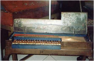
This report describes day by day the
entire process of building a copy of an anonymous clavichord in the collection
of the Nordiska Museet (number N264785), Stockholm, now deposited in the Musikmuseet. A
drawing (see picture below!) and a soundclip of this instrument is available
from Musikmuseet. The assignment, as given by Musikmuseet, was to build a
copy of this instrument and also to document the work in pictures and text. The
finished clavichord now has the inventory number X5414 in Musikmuseet,
Stockholm. The report follows in outline the building description which was
made by HansErik Svensson, but diverges in some details, for example in the
order in which the work was carried out. I'm greatly indebted to Stuart Frankel
who has made the translation from Swedish to English.
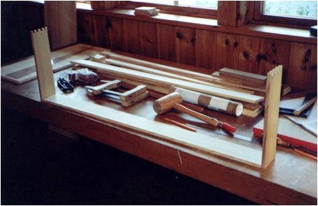
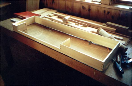
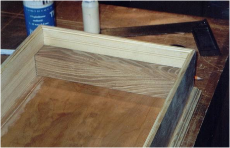
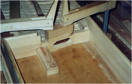
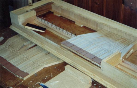
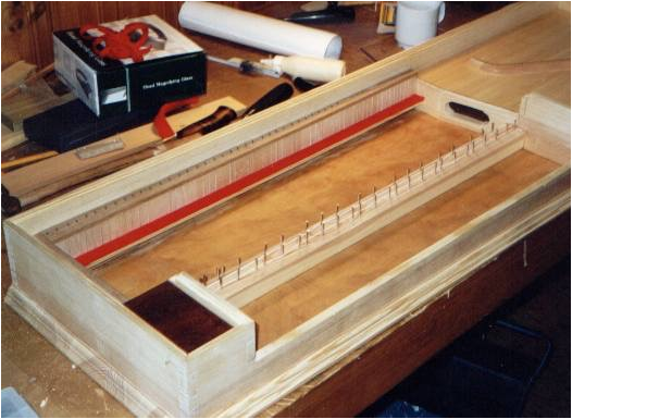
Day 1: July 26
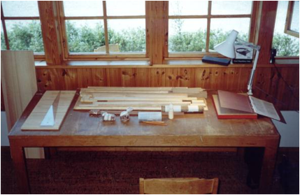
The points of departure for building the
clavichord were well-prepared materials and a detailed written description of
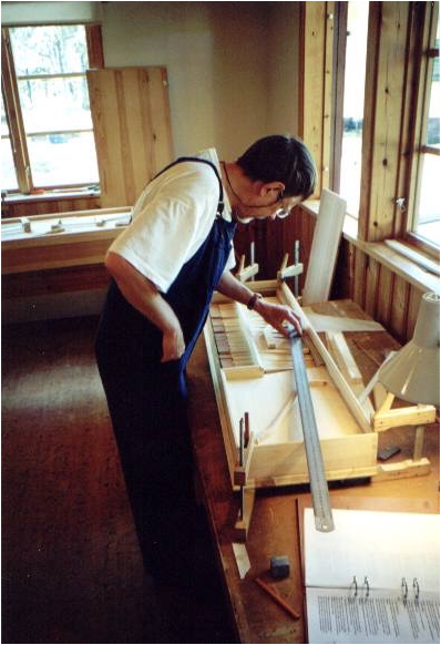
the construction. Right away it could be established that the quality of the
prepared material was very high. Picture 1.
Case (pine)
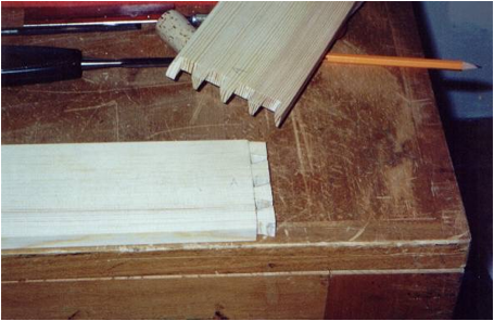
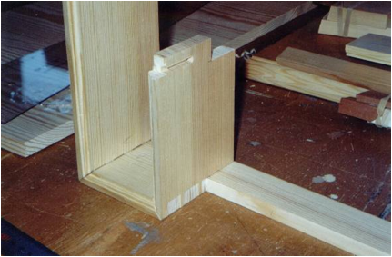
Dovetailing the four case corners
The first task was to make a corner. The
upper tenons were not sawed off entirely, but at a 45-degree angle. A pencil
line was drawn with the aid of a set-square 12 mm from the end on the inside of
the spine. The spine was fastened tightly to the table on its face and the side
piece was held so that its inside followed the pencil line and the upper edges
were level, as determined by the set-square. It was important that their upper
edges come to the same level, so if the sides were not exactly the same height,
the difference in level was planed down when the sides were glued on. With a
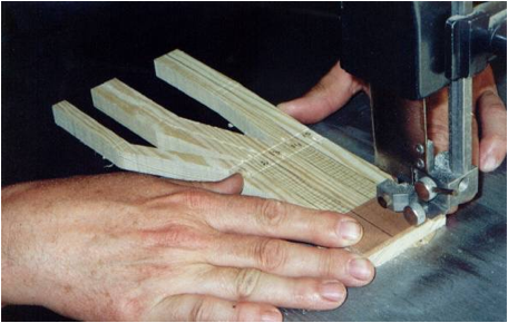
sharp lead point the tenons were traced out. I sawed slowly and very carefully
on a medium-large bandsaw along the pencil lines on the side where the tenon will
go in, without obliterating any of the line. The saw cut went just up to where
the pencil lines met. Many closely spaced cuts were sawn between the two lines.
These cuts were somewhat oblique, to obliterate the wood chips. All the rest of
the wood was sawn away within the pencil lines. If the saw cut did not end
correctly at the pencil line at some point, the saw blade was backed out along
the line and the saw teeth gnawed it away. The tendons on the tops of the side
pieces were cut at 45-degrees with a small saw. Corresponding pieces were sawn
out of the spine. The corner was carefully knocked together, and wood was
removed with a knife or chisel where it was in the way. The dovetail should be
tight but not need force to go together. Pictures 2-4.
Dovetailing the cheekpieces
First a notch was made in the front for
the keyboard. A pencil line was drawn with a set-square on the inside of the
front, 11.5 mm from the notch. The other side was scribed down to the notch.
Lines were drawn on the cheeks under the dovetail tenons along their undersides
and were sawn out, so that the sides would not prevent the cheekpieces from
reaching the corner. The
notch for the dovetail tenons was sawn out from the front. The corners were fit. Picture 6.
Groove and notch in the cheekpieces
Both cheekpieces have a routed groove for
the nameboard. The rounded end was cut straight with a narrow chisel. A notch was sawn in the cheeks'
upper edge to accommodate the nameboard. The downward saw cut followed along
the edge of the mark. The depth was a scant centimeter. Both keyboard cheeks have a notch at the bottom for the
balance rail. Lines were drawn 96 mm from the inside of the front and the
height of the balance rail from the bottom. The corners were
sawn out. Pictures 7-8.
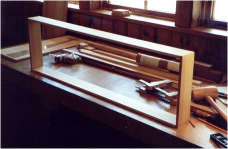
Screwing the case walls down
The assembled (not glued) case walls were
held tightly to the bottom so that the bottom extended out the same length in
front and on the sides. A check was made that the long sides were straight and
the corners at right angles. The
inside and outside of the case walls were traced along the bottom. Because a
long side curved, only the corners were traced. When the case walls were
removed from the bottom the correct cuts could be made with a straightedge.
The case walls were removed and screw holes
were drilled with a hand drill between the scribed lines along the bottom (2.0
mm). The screws were set about 5 cm from the corners and another screw put on
the long sides. The case walls were held fast in the same position as before
and holes drilled through the bottom holes into the case walls with a 2.0 mm
drill. The drill was drilled in 40 mm and a collar insured that the chuck
didn't bottom out. The case walls were removed and the holes in the bottom
drilled out to 3.5 mm. The walls and bottom were test-screwed together. The
rear wall was also checked. Picture 9.
The weather was fluctuating during the days but we took a brief dip in rather tepid water. Interesting conversations in connections with meal times on the new organization of the Statens Musiksamlingar (State Music Collections), music museums, music instruments, etc. In the evening we enjoyed a little concert by Mikko Korhonen who improvised on Bengt-Olof Sahlins Specken clavichord from 1979, the first clavichord built on Marholmen, together with Mikko Korhonen's own reconstruction of a medieval clavichord in Pythagorean tuning, based on a description and diagram of Henri Arnaut de Zwolle.
Day 2: July 27
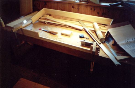
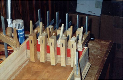
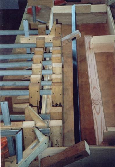
Gluing the case walls
First the spinel was screwed to the
bottom without glue. Glue was spread in the case-wall dovetails, the corners
pressed together or hit with a wooden mallet and adjusted if necessary, and the
walls were screwed fast to the bottom without glue.
Clamps were attached. Wooden blocks are
used behind the dovetails as guards to insure that the case walls' dovetails
were not prevented from pressing into the notch on the spine. Picture 10.
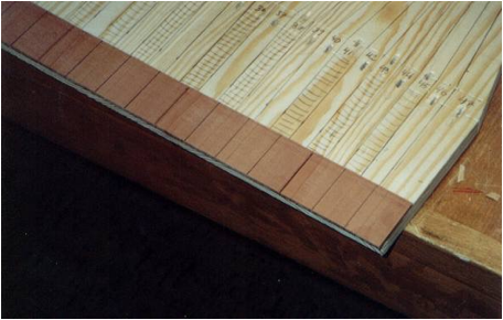
A line was drawn on the bottom along the spine to show where the bottom board should be cut. The dovetails were planed and sanded on their undersides where the case walls were removed from the bottom. A sander was used for this. The differences in levels underneath the case corners were planed away. The back edge of the bottom was sawn and planed.
Gluing the case walls to the bottom
Four of the screws near the corners were
set in so that they stuck up out of the bottom.
Glue was spread on the underedges of the
case walls, the walls were placed on the screws and I made sure the screws went
into the holes and then screwed them until a little opening remained. The
bottom was turned upside down and all the screws were screwed in. I pressed
carefully so that I knew that the screws went into the holes. All the screws
were turned hard, I turned the case right-side up and set clamps around. Picture 12.
After the glue dried, I checked that no screwhead protruded from the bottom. If one did, it was unscrewed, countersunk, and then screwed back in.
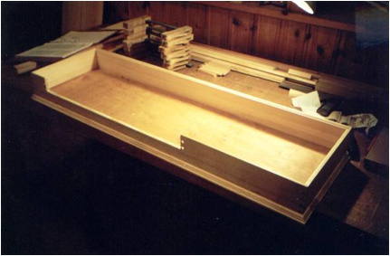
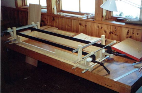
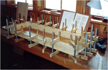
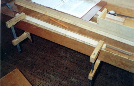
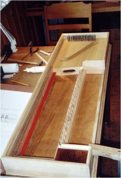
Internal structural members
Wrestplank (oak)
The wrestplank was cut so that there were
a few mm between it and the front and spine. Then glue remnants and other gunk
in the corners were removed and the wrestplank put back so that it fit as well
as possible. Picture 13.
With a chisel a notch was cut for the top
of the wrestplank about a cm wide and a couple of mm deep, to give the bass end
of the bridge a little more space to resonate on the bottom. I checked that the
notch did not come too close to where the wrestpins would go. A pencil line was
scribed on the case wall and bottom around the wrestplank. A lot of glue was
spread inside the pencil lines and a little on the wrestplank, the wrestplank
was placed there and as many clamps between the case walls and bottom as would
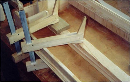
fit were set. Picture 14.
The glue which was forced out onto the case was removed without smearing the top of the case where it would be noticeable later.
Balance rail
A notch was made in the left end for the
left hitchpin-rail support which is as deep at the support's top surface,
coming 61 mm over the bottom. There must be no play in the notch. Three 2-mm
holes were bored from above through the centerline of the balance rail and
through the bottom. The holes in the bottom were then drilled out with a 3.5 mm
drill.
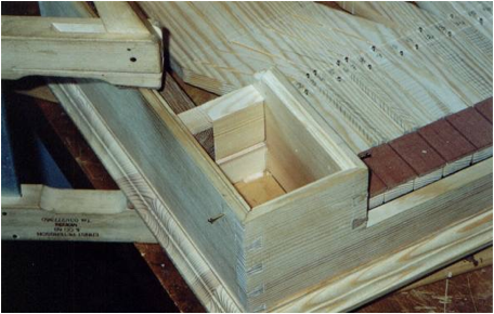
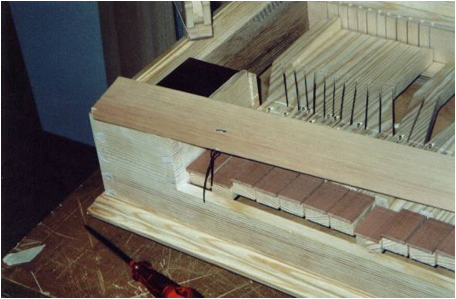
Rear framing
The point where the backrail meets the
bellyrail is 674 mm from the inside of the left case wall. A line was drawn at
a right angle up from the bottom on the inside of the spine. This defines where
the backrail and hitchpin rail will be removed, and also the exact position for
the soundboard and template where the holes for bridge placement will be fixed. The backrail (lime) was cut. It is
674 mm long by 22 mm at the wide end and 14.5 mm at the narrow end. Picture 16.
The notch in the hitchpin block was sawn. The hitchpin rail and the backrail will be level with the left of the hitchpin block and there must be no error here. Because the backrail is tapered, the crosscut is not at a right angle. Changing weather, but mostly sunny. A dip before coffee. A little playing on guitar and baroque lute waiting for the glue on the wrestplank to dry. Evening concert in the villa with Mikko Korhonen who played exclusively on the schools' five-octave clavichord.
Day 3: July 28
The backrail was clamped tight against
the level bottom with the basswood up, so that it fit closely everywhere, and
the hitchpin rail was placed as best as possible. I made sure, however, that
the hitchpin rail was long enough to reach the hitchpin block. The hitchpin
rail was planed narrower where it extended too much beyond the backrail at one
place. The hitchpin block was shortened so that its front was level with the
front edge of the balance rail. The keybed will be as long as the backrail.
This will be 40 mm at the wide end and 30 mm at the narrow. This was sawn to
the right length. The hitchpin block, balance rail, and hitchpin rail were
fastened tightly into position, the template for the hitchpins laid on top, and
indications of where to drill were punched with a special marker. Picture 17.
The parts were unfastened and holes
drilled for the hitchpin in the hitchpin block and rail, at a 10-degree angle
from vertical. The table on the drillpress was angled. The pins will lean back
in a precise direction. Masking tape on the drill table indicated the furthest
line to be drilled on the hitchpin block and hitchpin rail which gave the right
pin angles. The holes were drilled in the hitchpin block with a 1.5 mm drill,
30 mm deep. First they were drilled halfway, the drill removed and the chips
poked out of the hole with a nail, and the drilling then continued. I changed
to a 1.6 mm drill and drilled 30 mm deep. Actually, the holes should have been
7 mm deep. The hitchpin rail was drilled first with a 1.5 mm then with a 1.6 mm
drill. The first drillings were rather unnecessary, but I read the instructions
carelessly. The hitchpin block and rail were not finished. The hitchpins were
driven into the block with a wood-handled brass mandrel to a height of about 3
mm. Picture 18.
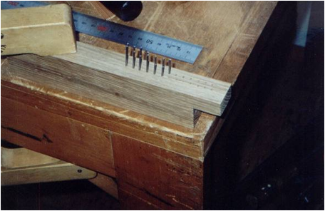
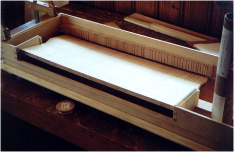
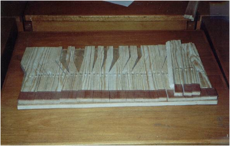
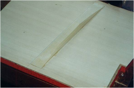
Rack
The slots on the rack were marked with a
lead pencil according to the rack template for the desired fretting system. The
template's treble end must line up with that of the backrail. A set-square was
used and lines were drawn between the pencil dots where the rack slots should
be sawn, and also on the top at a right angle to the back edge. A pencil line was drawn on the top
of the backrail about 6 mm from the front edge.
A hole was drilled through the backrail
from the top where each rack slot crossed this line. A 4-mm gimlet was used in
the drill press. I started carefully so that the drill wouldn't drive off
course. The drive belts drove at too high speed. Each slot was sawn with a
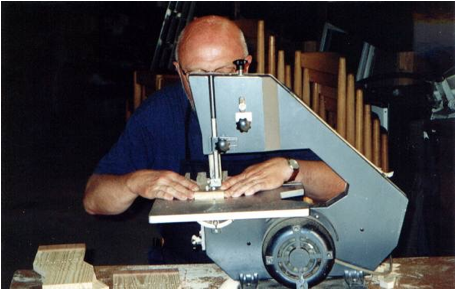
medium-size bandsaw with three sawcuts, one perpendicular and two angled. I was
careful not to let the saw blade touch the front of the rack. This lessens the
friction between the rack tongue and the rack, and the tongues work even if
their aim isn't perfect. Picture 19.
The rack was turned up and down so that all the cuts would be sawn on the same bandsaw.
I checked that the slot was made just the
right width in front with a rack-tongue slip. The hole was cleaned with a round
and flat nailfile. The slot was pressed out with a 1.3-mm needle. The rack was glued against the
spine. Pictures 21-24.
Balance rail fitted in. Picture 15.
Evening concert with Mikko Korhonen who devoted himself entirely to his own instrument, an anonymous clavichord built at Marholmen.
Day 4: July 29
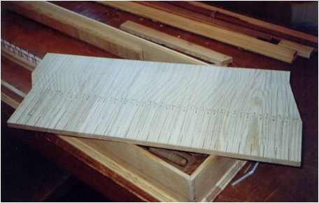
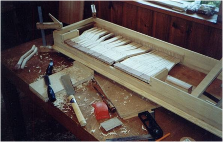
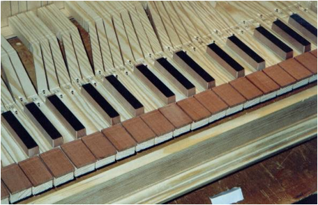
Keyboard (pine)
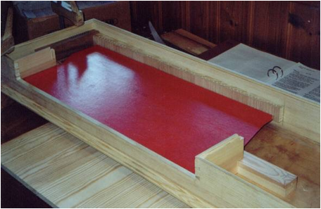
Fitting
The red keyboard template was test-fitted
in the instrument. There should be 1-2 mm. play between the template and the
rack. Picture 25.
The template was laid on the keyblank
along the machine-planed back edge and traced out. The keyblank's short sides were sawn
so that they could be laid down between the cheeks. Picture 26.
The keyblank was fastened in the right
position. Marks were set on the keyblank and along both cheeks 122 mm and 137
mm from the outside of the front for the position of the holes on the balance
rail in the bass and treble. Marks were also set 48 mm in from the outside of
the front on the cheeks and on the keyblank. The marks showed the border
between the naturals and the accidentals. The keyblank was taken out and lines
were scribed on the balance rail and the blank for the naturals. A pencil line
was also drawn 34 mm in front of the line on the naturals' keyblank and the
front edged was planed by machine to this line. The template for the key-cover slips
was laid along the keyblank's front edge with the same amount of space on both
sides between the cheeks and the rear pencilmarks scribed for the two lowest
and the two highest keys. A set-square was laid on the front edge and lines
were drawn from these outer keys to the rearmost lines on the balance rail. Pictures 27-28.
An awl mark was made in the front balance-rail line between the 2nd-lowest (F) and the 2nd-highest (b2) keys. I drilled a 2.00 mm hole through the marks at right angles through the keybed.
Rack tongues
The keyblank was laid in the instrument
with the balance rail screwed down tight; it was oriented in precisely the
right place and nails were pushed down through the holes to fix the keyblank's
position on the balance rail. A knife was stuck in each rack slot and with the
cutting-edge a mark was pressed into the back edge of the keyblank. A right
angle was measured from the front edge out 83 and 90 mm from the back of the
lowest keys at the rack-tongue holes, and 39 and 46 mm from the back of the
highest key. The keyblank was taken out and two lines scribed over the blank
between the markings. The front showed where the keys are angled, the rear
where the cut begins. A line was scribed between the knife mark and the nearest
scribed line along a set-square set along the front edge of the keyblank.
One-by-one the tangents, which hit the strings, will be placed in these scribed
lines. A line was drawn with the set-square on the back edge at each knife mark
to show where the hole for the rack tongues will be punched. Holes were punched
for the tongues, with the keyblank's front edge held against the steady,
horizontal base. The holes will be at right angles to the front edge, so the
tool was therefore held plumb straight. The edges of the corners were fastened
on each end by rack-tongue slips, and the right length was cut off and the rack
tongues were pounded tightly in with the front end down in the hole. They were
pounded in with a special wooden block. The tongues were filed on both sides,
top and bottom, so they had their full width only in the middle. While the
keyblank was still whole, it was roughly sanded. An evening concert with Mikko
Korhonen on my Specken clavichord. Weather sunny and warm. A dip before lunch,
coffee, and dinner.
Day 5: July 30
Marking out the keys
A pencil mark was made by eyeing back on
the keyblank in the middle of the scribed lines. In order to work, for the keys
to be spaced correctly with E and B unfretted in the middle of the keyboard,
one part of the scribed lines must wind up outside the center of the keys. A
plastic-film keyboard template, previously used for scribing out the keys, was
pressed into service again.
Pencil lines were drawn along the
set-square as before, up to the second scribed line. The lines show the back
edges of the keys. The template for scribing the keyboard was fastened down,
the keys marked and scribed with the set-square against the front edge. Lines
were drawn to the back line scribed on the balance rail. The slanted lines
outlining the keys were drawn in the middle of the keyblank. Picture 32.
Balance holes and pins
I marked with a pencil all the keys, the
accidentals (back scribed line) and naturals (front scribed line), in order to
be able to keep them in order easily. For the balance holes, an awl mark was
made along the two scribed lines and in the middle of each key.
Outside the instrument, with the keyblank
tightly pinned to the balance rail, holes were drilled (2.0-mm drill) through
the keyblank down into the balance rail (total 33 mm deep). A hand drill was
used and a special water level was attached for plumb-straight drilling. The
balance holes were also drilled in the balance rail. The bevels were planed up to the
pinholes in the balance rail. The cheeks were glued. Balance rail glued and
screwed in. Picture 30.
Balance pins were driven in. A measuring
block was used to get the right height (17 mm). Picture 31.
Threads were put on the balance pins to act as bushings. They were fastened with wooden nails and pins in the bass and treble. Separate threads were used for the front and back balance pins. The threads go on every other side, or one pair of pins in each octave, so that they don't interfere with the pins. The holes in the keys were chiseled out with the help of a special tool and a little chisel. Evening concert with Mikko Korhonen who played on Anna Axbergs recently completed Wåhlström clavichord and on my Specken clavichord.
Day 6: July 31
The balance holes were punched. For better precision, the oblong holes were first cut at the top with a little chisel, but smaller, at least in surface area, than the final hole would be. After that the holes were punched. The holes were widened from above with a special tool with a 2.6-mm point and a metal handle. The keys were numbered from bass to treble (1-47). The numbers were written between the scribed lines on the balance rail.
Gluing the pinblock
Masking tape was put on the case walls.
The pinblock was glued and pressed against the side wall, against the spine,
and down against the balance rail and rack (with a support block underneath).
The glue was spread first on the pin block, then on the case walls and in the
notches. Picture 33.
Key covers (pear, original boxwood)
A ruler was fastened tightly on the
keyblank along the back edge of the natural keys. The covers were laid out as
desired. The planed edge should be turned against the ruler. All the splices
were laid between the keys. The
covers were glued. I made sure they didn't slide when they were clamped down. Pictures 34- 35.
The front edge was shifted when the glue had dried. A completely smooth edge is necessary to cut the keys right.
Scribing the decorative lines on the
naturals
The seam separating the natural and
accidental keyblanks corresponds with a scribed line. In front of this line three further
lines are scribed, the space between them being 1.5, 3, and 1.5 mm.
A hobby knife and ruler were used. I drew as
many times as needed to give the full depth the whole way. Pictures 36-37.
Tracing out the keyboard
Pencil lines were scribed in the seams on
the keyblank for the naturals. These pencil lines were examined through the
keyboard template, and I judged that all the front key-cover slips looked like
they had same width.
Sawing them out
The keyblank was sawn out. All the straight saw cuts were sawn
from the front and the back on a small bandsaw. I was very careful about the
covers when I made the sawcuts from the front. The accidentals were sawn free from the naturals with a
fret saw. Because the
keyblank was large, all the cuts couldn't be made at one time. The blank was
sawn apart between e and f, and between b and c, in all the octaves. All the
straight cuts were sawn from the front and from the back. The front edges of
the accidentals were all fret-sawn a bit in back of the naturals. The keys were sawn
apart. Pictures 38-40.
Evening concert with Mikko Korhonen on his own Wåhlström and anonymous clavichords.
Day 7: August 1
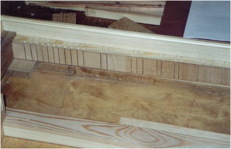
Putting the naturals in
All the naturals were sawn on a slant,
since the key cover is wider than the base of the key, without any of the blank
itself being sawn away. A 60-degree angle was chosen. A Japanese saw and a
little backsaw was used. The sides of the keys were roughly planed.
Picture 41.
Putting the accidentals in
All the accidentals were cut away in
front at a 75-80 degree angle so that the pencil marks just disappeared.
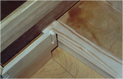
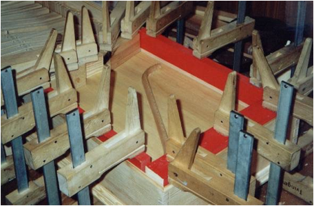
Bellyrail
The back of the bellyrail was correctly
sized so that the longer side was 65 mm. Glue was spread on the underside and ends, and a piece of
wood was laid on top to come up to the level of the case walls and clamped
tightly downward, towards the back, and against the rack. I made sure the belly
rail was at a right angle to the back wall. Picture 42.
The longer part of the bellyrail was sawn
off so that it fit correctly between the higher side of the keyboard and the
shorter part of the bellyrail. A notch was sawn for the balance rail. The mousehole was scribed according
to the template. The circle were drilled with a special 11-mm drill. I used the
drill press and drilled first from the outside of the belly rail so that the
drill point just went through. The bit was changed and drilled from the other
hole. A row of smaller holes
was quickly drilled in the upper and lower edges. I chiseled out with a chisel
and cut clean with a knife. The
belly-rail sections were glued. Picture 44.
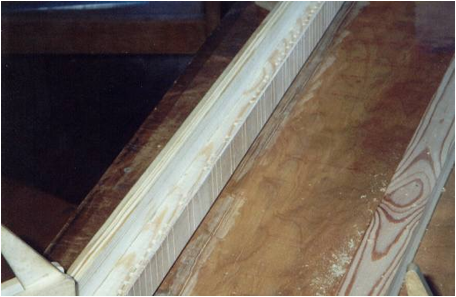
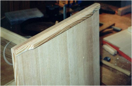
Nameboard
The nameboard was sawn to the right
length and whatever had to be removed was scribed. I cut away with a chisel and
gradually tested its fit in the instrument. So as not to make a ledge where the moldings meet, a
moulding was sculptured which connected to the moulding of the cheeks and gave
the impression of a mitered corner. Picture 43.
The evening was devoted to a trip to Furusund and an estimable concert with the ensemble Mare Balticum from Musik i Skåne (Music in Scania). The concert took place out of doors in a wonderful summer evening before large and enthusiastic audience.
Day 8: August 2
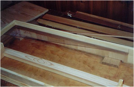
Soundboard liners
Battens were cut to fit between the
bellyrail and wrestplank, the wrestplank and right cheek, and along the
keyboard side back to the bellyrail. Picture 45.
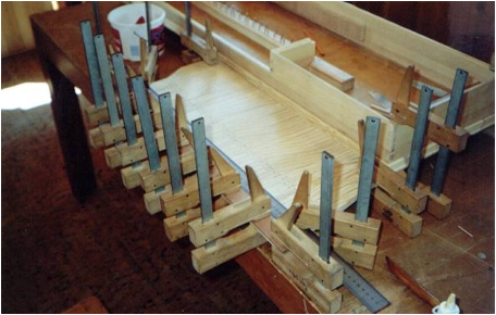
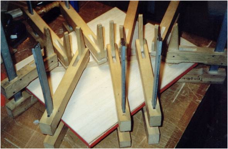
The battens were glued in and I made sure that they stayed in the right position, level with the bellyrail and wrestplank, when the clamps were tightened. The level of the joints was adjusted all around after the gluing. Where the support was too high, it was lowered with a sanding block.
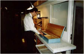
Toolbox lid
I made the toolbox lid the right size so
that it was even with the back edge of the toolbox and also with the back edge
of the nameboard. The
width was adjusted to fit the compartment. The lid was veneered with highly figured walnut, smoothed
and finished with raw linseed oil and beeswax on the top. Picture 46.
I drilled with a 1.6 mm drill very straight through the case walls, placed the toolbox lid in the right positions, knocked the axle in a bit, and checked that lid opened and shut correctly. The axle was taken out and a hole was drilled in the lid with a 1.5 mm drill. The axle was put in all the way before the instrument was painted.
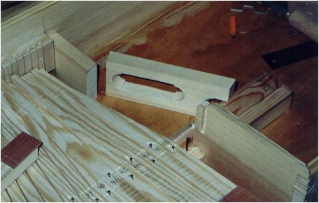
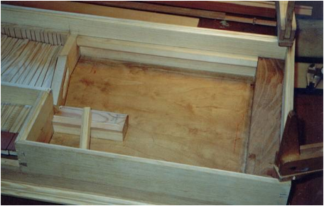
Block
A block was cut so that it could driven
in between the hitchpin block and the left cheek. Also, a small piece of wood
was fit in so that the toolbox lid would go in its original position. The block and small piece of wood were
glued. A piece of wood which reaches over the case walls was set on top to
facilitate clamping. Glue was spread on the hitchpin rail, balance rail, and
cheek, not on the block. Picture 47.
Flap
I checked that the flap fitted well in the opening in the case. Picture 48.
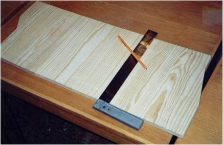
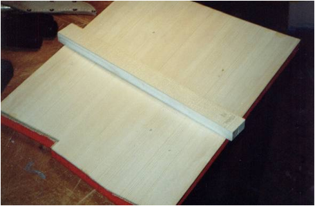
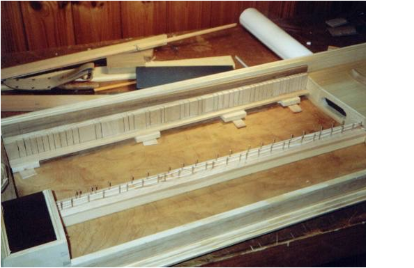
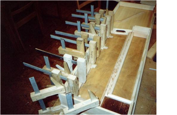
Soundboard
(spruce)
A pencil line was drawn in the middle of the soundboard at right angle
to the grain. A cross mark was set in each end so
that it would remain even when the soundboard was sawn out to an exact
measurement. The space between the markings was measured exactly and the
measurement written down. The
soundboard was put into a drying cabinet and taken out after a couple of hours.
The distance between the markings was measured again and the new value written
down. The drying was continued until the board stopped shrinking.
The fit of the soundboard template was
checked in the instrument. Picture 49.
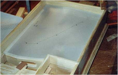
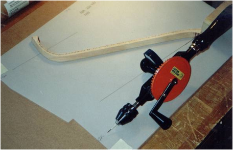
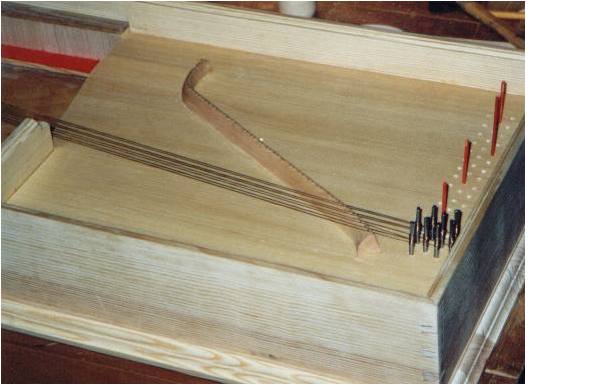
The soundboard outline was scribed according to the template with possible corrections. The soundboard was sawn out. The soundboard was fitted so that it fit precisely. The template was laid on the soundboard. I marked holes for positioning the bridge with an awl through the template. Holes were drilled (3.0 mm) in the soundboard bridge markings. The position for the rib (or ribs) was marked on the underside.
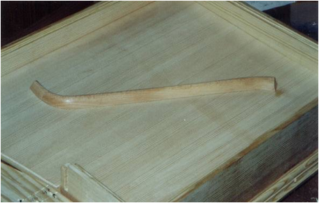
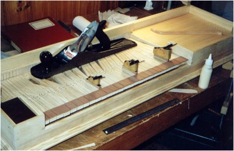
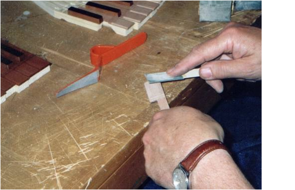
Bridge (sycamore)
The bridge was screwed tightly to the soundboard from underneath. Picture 57.
The soundboard was laid in the instrument. The template-strip for the
bridgepins was attached to a plastic angle and the measurements checked. Picture 51.
The positions for the bridge pins were marked from the template-strip with a pencil.
The soundboard was taken out, the bridge unscrewed, and a mark made in
each pencil cross with special markers. I didn't use the
drill press since it was hard to get the drill centerd and on an even level. I
used the hand drill instead. The
drill (0.9 mm) was set in and I checked that it was correctly centerd. Its
depth was set to 7 mm. I
drilled so that the angle the whole time was in the direction of the bridge at
the drilled hole. Picture 54.
The upper side of the bridge was colored with a pencil and a line was
drawn on its left side (outer curve) a scant millimeter under the upper edge. The upper side of
the bridge was fastened at an angle down on the pencil line with a angled
Sandplate (sanding block). The pencil mark should disappear around the
bridgepin holes but remain along the ridge. Picture 56.
The side of the bridge was rounded if possible a bit against the bevel so that the bevel surface would not be so wide. The bridge ends were cut with a Japanese saw. I fine-cut with a sharp knife. The bridge was finished with shellac, but not on the underside which will be glued. The bridge ridge was waxed with beeswax, spread on with a finger, let dry, and then rubbed with a rag. The procedure was repeated a couple of times. The waxing was done so that the strings would slip more easily, which would facilitate tuning and improve the tuning stability.
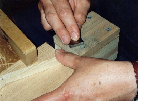
Filing the
tangents
The tangents were clamped fast in a screw clamp between pieces of wood
(or in an aluminum clamp) so that the jaws didn't make marks, and the long
sides were filed with a simple-ridged file. I was careful not to damage the
tops. The warm night was devoted to an evening dip with Björn
and Olle and then continued work until midnight.
Day 9: August 3
I used a special tool to ream out the holes in the keys for the balance
pins. Picture 52.
I checked that the keys moved easily with the help of a piece of wood which was furnished with a balance pin. This was clamped tightly to the bench and I tried the key's path. I took out the future neighboring keys so that they could not disturb things and I put each key in its place in the instrument. The rack tongues were cut or filed so that the key moved without binding but with as little sideways play as possible. The tongue will be smaller towards the top and bottom and have its full width only in the middle. This would not work unless the tongue sits exactly vertically. The key should now move freely and easily.
Day 10: August 4
The nearest straight keys were laid in and I cut and planed them free from each other.
When all the natural keys were laid in, their sides were planed so that
all the gaps between their fronts were just right and the same size. The backrail was
set in place by being pressed up to the rack, sitting on blocks. Picture 53.
The accidentals were smoothed. The edges were carefully rounded on top and in front.
The soundboard was smoothed. The bridge was
glued. I used a piece of chipboard with a notch for the bridge curves.
First I did a dry run. The bridge was
screwed in and I used as many clamps as would fit. The right amount of glue was spread on the underside of
the bridge, it was placed on the screws which stuck up and I let the screws
help position the bridge, then the whole bridge was pressed down, all the
screws screwed in and clamps put on. Picture 58.
The bridge was masked with masking tape. The soundboard was finished.
Very thin shellac was used, flowing from brush strokes with the grain,
but not so much that it ran. I polished it with steelwool after it dried.
Day 11: August 5
The bridge pins are made of 1 mm brass wire. I put the wire into each
hole into a special bridge-pin workblock and cut it off straight across with
clippers. I filed over the whole workblock so that the pins made a level
surface. The workblock was turned over and the pins knocked out. 62 pins were
needed. A special tool was used to tap the pins into the pre-drilled holes in
the bridge. First the pins were pushed down some mm and I felt to make sure
they were tight in the hole at the right angle, then I hammered carefully with
small taps and listened to the sound when the pin reached the bottom. The pins
were bent with a special tool so that they sloped at right angles to the
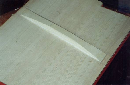
direction of the strings. The pins were filed to an even height with a file. The rib was glued
and shaped. The notched chipboard for the bridge was used. I also made sure
that the rib ends didn't protrude beyond the soundboard. Pictures 59, 61, and 62.
Old clavichords often have thin strips of parchment glued under the ends
of the bridge across the grain. Paper strips were glued in the same way. The soundboard was
glued in. Picture 63.
Lid rails
The rails for the sides of the lid were cut to the right length I tried to tap
them into place. I sanded the lid notch where it fit too tightly.
The ends were shaped. The rails were glued down. I glued only the front edge and
a little on the back edge so that the lid could twist without cracking. Picture 60.
Flap
The flap was furnished with a threaded
hinge. Holes were marked
with a awl in the outer corner of the bottom edge and drilled with a 2 mm drill
at a 45-degree angle. The flap was held in place and corresponding holes were
marked in the case. I marked with an awl and drilled at 45 degrees through the
case. Two threads folded in the middle were set together and I pressed to make
the twisted knots small and tight. The straight parts were cut correctly, a
little unevenly, if the thread wouldn't go through the flap. For now, the
hinges will be allowed to stick out on the inside of the case, so the lid can
be removed for painting. Pictures 64-65.
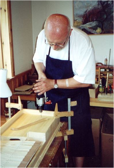
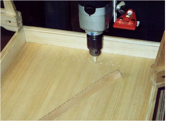
Wrestpin holes
The wrestpin template was laid against
the back and side walls and fastened with a pin in the treble and bass. Picture 66.

All the holes were marked with a special
marker .A rod with a
point surrounded by a ring was fastened into the hand drill. The point was set in each mark and I let the ring cut the
fibers so that the soundboard wood did not shred when drilled. Holes were drilled with a 2.6 mm drill 20 mm deep at a
5-degree angle. Then with a
3.3 mm drill, I drilled 5 mm deep. Picture 67-68.
Arne Lindberg and I skipped Mikko Korhonen's evening concert in order to try out Mikael's newly completed lute. We played some duets on Mikael's and my lutes from the 1984 Marholmen course.
Day 12: August 6
Keyboard
The two accidentals which are to be
divided were cut. The
accidentals were put in position and cut in the back so that they had the right
clearance with the naturals in the front and against the nameboard in the back.
First all the g-sharps were glued; these
were placed in the middle of the gaps between the naturals. Picture 69.
Glue was spread under the accidentals,
they were set in place and pressed by hand, sometimes with a little press. I
checked that they were set correctly, and let them dry. The template was used and the
remaining accidentals were glued. Picture 73.
Balancing the keys
I sawed and cut away in front on the
undersides of all the naturals. Evening concert (public) in the church at Länna
with Mikko Korhonen on organ and on my Specken clavichord. Arne Lindberg and I
played two lute duets (La Rossignol and My Lord Willoughbies Welcome Home) on
our new lutes. Picture 76.
Day 13: August 7
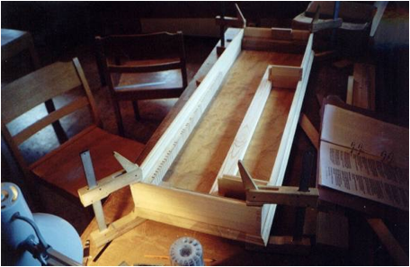
The natural tails were glued. Those for the D keys are wider than the others. I planed to the width which gave the right clearance and pressed down. The side edges of the naturals were beveled from the front to the first scribe line. The beveled edges were rounded with a knife and sanding sticks.
Hitchpins
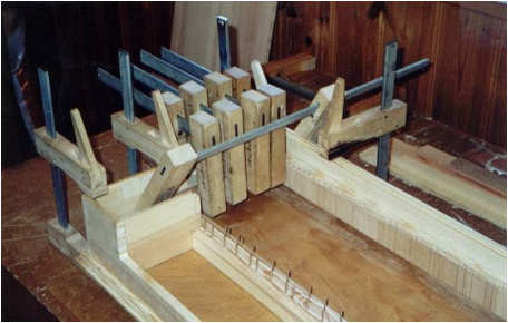
The hitchpin rail was glued. It was
clamped against the spine, the rack and the hitchpin block. Blocks were driven
in under the rack to give support against the bottom. I made sure that glue
didn't get in the holes, and glued the support blocks. Pictures 83-84.
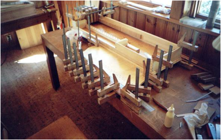
The backrail was glued against the spine
and the rack. It was pressed against the rack with blocks. The backrail cloth was fastened on
with a number of dots of glue. Picture 85.
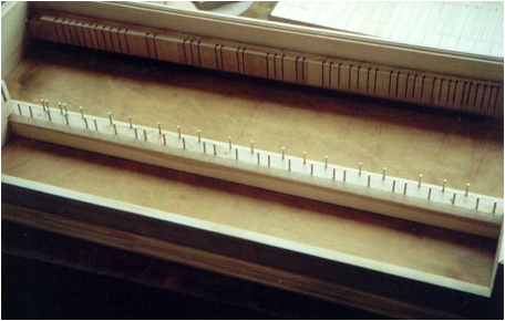
The remaining hitchpins were driven in with a wood-handled brass mandrel. Support blocks were set under the backrail.
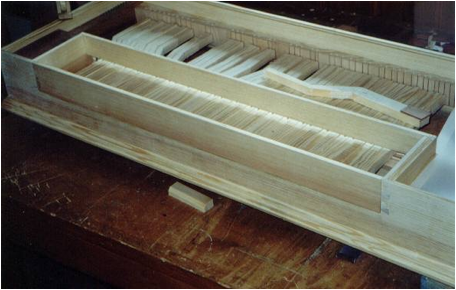
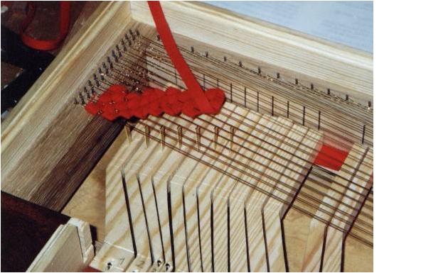
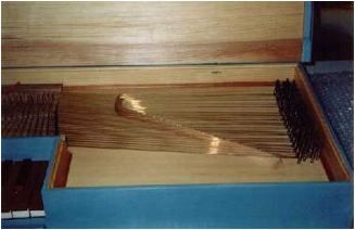
Stringing
I took as many wrestpins as would be used
for the first string gauge. When they had been used it would be time to change
gauges, and so I laid out as many pins as would be needed. I wanted to have a red felt mark on
the A pins so I put red pins in all the holes which would have the felt marks
so they wouldn't be left out. The
loop-making machine was fastened down with two wooden clamps, the left one
opening up and down. The wire coil was hung over the metal bar sticking up out
of the left clamp, and a 10-cm end of the wired was wound around the machine's
hook. The end was twisted counterclockwise turning around the wire and I
stopped about 3 cm from the hook by bending the end at a right angle out from
the wire. The end and wire were held fast with pliers and the machine pedaled
again. I let it whirl until there were enough windings.
The wire was stretched straight out from
the hook and the end bent back and forth along the wire until either it broke
off or I snipped it off 4-5 mm from the windings with wire cutters. Acceptable loops were hooked on
their hitchpins and the string placed on the correct bridgepin. The schedule
for string length beyond the wrestpins determined where the wire would be cut
with wire cutters.
The wrestpin was held horizontally with
the flat end to the right and with the string along the wrestpin with its end
even with the bottom of the wrestpin. The wrestpin was rolled in the same direction as one
pedals a bicycle and I let the string turns go over the string ends and held
them to the pin. The string must at all times be held in tension until the pin
is hammered into its hole.
At the beginning, one hand must hold both
the end of the string and the rolled-up coils when the other hand had to take a
new grip. After several turns, the string was fastened to the pin and then it
wound a little more freely, but the string had to be held under tension the
whole time, otherwise the winding would immediately come loose. When there were about 5 centimeters
left to the hole, the end of the string was taken off so that the last few windings
went around only the pin and not also over the end of the string, which would
make the string easier to remove in the future. Taking a firm grip on the windings with my right hand, I
bent the end of the string back and forth until it broke. The string was held
under tension the whole time. When
there were a couple of centimeters left until the hole, the last windings were
spaced out, the pin was turned right and put down into the hole. The string was
tightened as necessary with the tuning wrench and the pin hammered in so that
it held fast. If necessary, the height of the level where the string leaves the
pin could be adjusted; after that the pin was tapped down to the right level. I
checked that the string was tense enough before I went on to the next step. Pictures 86-87.
Evening concert with Mikko Korhonen who played Ragnar Köhlin's Specken clavichord.
Day 14: August 8
After sanding and fine adjustments, the
key coverings on the naturals and accidentals (but not the ebony coverings)
were coated with clear so-called Danish Oil. I kept putting on oil for it to
absorb until my patience gave out. The excess was wiped off and I let the oil
dry. Pictures 88-89.
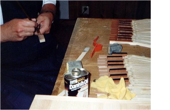
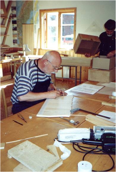
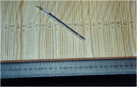
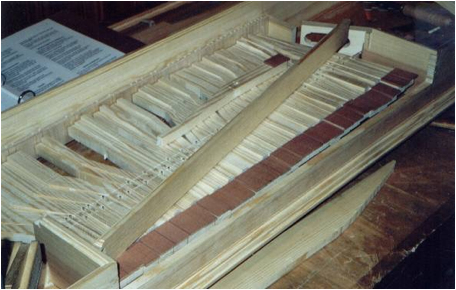
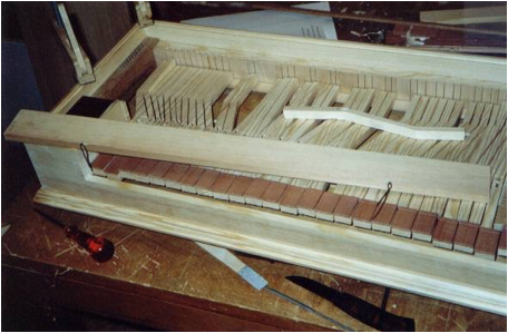
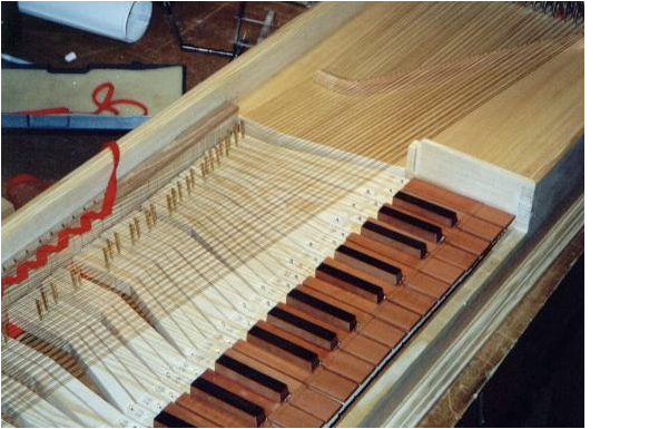
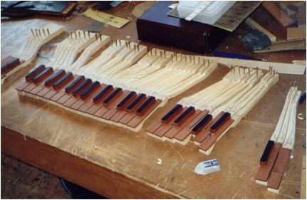
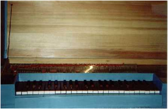
The tangents were sorted by size, the widest in the bass. I started installing the tangents from the bass. A marking tool was set so that the pin extended between the strings in the relevant stringpair and could press a mark in the scribed line on the key. Unfretted keys got the tangent in the middle of their scribed line. The scribing was done according to the rack template where the strike point had been calculated according to string lengths on the scribe lines used for measuring. I therefore made sure that the strike point came entirely from the true string length. A supplement to the instructions described how the calculation was made with the help of a calculator. I set the striking points by compass with the aid of vernier calipers. The compass was laid flat on the keys. I wrote the values in a table, which was also found in the supplement. One tangent was done at a time, at least to start with, so that the method and the result could be validated. The hole was marked and punched. I tapped the punch down a bit at a time and loosened it in between, so that it didn't get fastened too tightly. It was rocked loose lengthwise, never crosswise. The holes were punched next through the keys. The edge of the tangent against the sounding part of the string must be clean and sharp. I felt against a nail which edge which sharpest. The tangent was tapped in with a wood block to a height of 20 mm. The tangent was polished in a special tool to make an even and smooth contact surface.
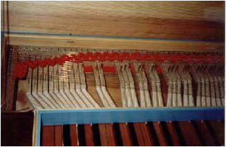
Listing
The listing was woven through the strings
and I made sure that the tangets hit correctly. The listing was woven alternately
under and over the string pairs with a few fairly hard, tight loops. One or two
string pairs per loop gave a steadier and less wobbly touch, but also a little
stiffer and with a weaker tone. So that the two strings in the pair wouldn't lie
too closely to each other, another cloth was inserted between the strings in
the pair and between the woven listing and the tangents. The distance was
tested. Pictures 90-91.
Mikko Korhonen played a concert in the evening on his quite recent clavichord, a 5-octave instrument built according to principles from the smaller Specken clavichord. Fantastic instrument and fantastic music!
Day 15: August 9
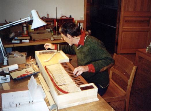
I continued with the tangents and weaving
the listing. Together with HansErik Svensson, I made many adjustments and
corrections. After all the tangets were tapped in, we started to tune the
instruments. Pictures 92, 95, and 98.
Soundboard moldings
The moulding is the same as that of the
case walls and runs the same length. The moulding ends even with the right cheek.
At the rack it is angled straight, and ends
even with the rack's edge. The
corners were made tight and pretty. The moldings and insides of the case were finished with
raw linseed oil.
Lid
The lid was held so that it extended out
the right amount over the front case wall (about 5 mm). A line was drawn on the
lid's underside along the spine. The edges were planed by machine.
Lid hinges
The lid on the original had three hinges,
one 146 mm from the left outer corner, one 493 mm from the left outer corner,
and one 131 mm from the right outer corner. Such hinges were made and installed
on the lid and back of the case.
Lid cord
The lid cord was fastened with a staple
in the pin block and a staple in the lid. The original position on the pinblock
appeared on the drawing; the lid fastening was missing because that part of the
lid is gone. The original thus now has the lid cord on the right side. To make the staples look old, they
were made of bent and hammered iron wire. I started first with a 2 mm drill. The lid cord was knotted tight. The lid must not tilt back
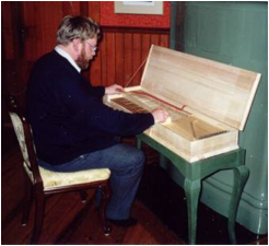
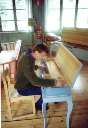
too far. Evening inaugural
concert on the ready clavichord. Because of the extremely high humidity
(70-80%) there were problems with tuning stability and some of the tangents'
functioning. Picture 100.
Day 16: August 19.
Carving the key levers
From the scribed lines back until just
before where the key bends a concave knife cut is carved from the outer edge
and down against the ridge but so that there was a ledge between the "ski point"-like
cut on the bottom and the ridge. To make a ledge on top, the ridge on the key must lie a
little under the level of the top surface. Therefore the ridge surface of one
side was first cut somewhat beyond the midline of the key. When the opposite ridge
surface was then cut so its back wound up in the middle of the key, it was also
somewhat lower in level. In
front, the ridge was finished by knife in a gentle curve going up to the
surface at the back line of balance-pin holes. Previously I had cut and planed the right clearance
between all the keys in back of the nameboard. A scribed or pencil line was drawn near the middle of the
keys where the ledge will be.
Lines were drawn along the sides of the
keys with a special scribing tool (a wood block with a screw) Two sawcuts with a little backsaw in
the scribed line determined the length of the ridge in the back. Each cut was
sawn almost until the middle of the key and to the scribed lines on the side.
With a chisel (or knife) the sides of the
ridge were cut to the width of the markings. First the ends against the sawcuts
were cut. Then I cut along the entire ridge with the grain, not against.
Because the ridge would be cut down to "ski points"at the back, the
ridge cuts were started a bit in front of the sawcuts. Then the second ridge side was cut in the same manner. I
cut far enough in so that the back of the ridge came to the middle of the key.
Since the second side was cut a little beyond the middle, the ridge wound up
lying a little lower than the surrounding. Picture 102.
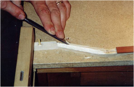
"Ski points" were cut with a
small knife between the scribed lines and the saw cuts. Picture 106.
After sanding, the clavichord was painted
light blue with oil paints (pigments: Paris blue, titanium white, and Picture
119.
Day 17 - August 11
Gluing the soundboard moldings
The corners were made close and nicely
even. During the gluing
a line of glue was put in the corner between the soundboard and the case and
the moulding pressed in place by hand. After a couple of minutes I checked it and pressed a
little more. Evening concert
with Mikko Korhonen who played on Bengt-Olof Sahlin's adjusted Specken
clavichord and his own newly built one.
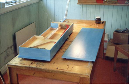
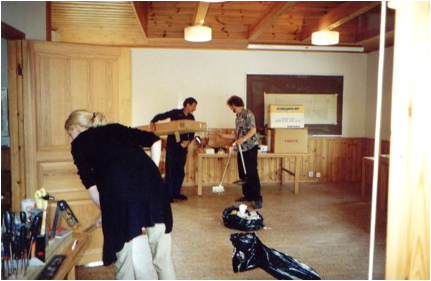
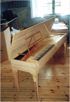
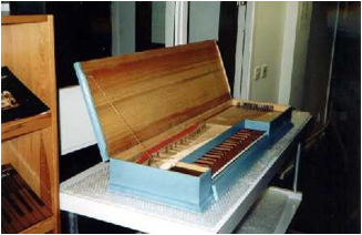
Day 18: August 12
Morning was devoted to cleaning out and
tidying up the workplace. Pictures 121 and 123.
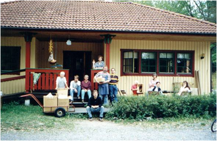
Following afternoon coffee, all the
instruments were set up in the lecture hall for testing. Pictures 127-131.
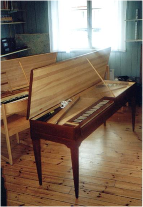
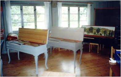
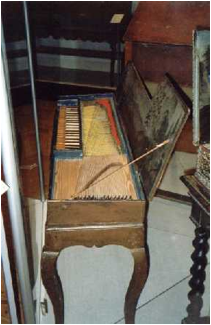
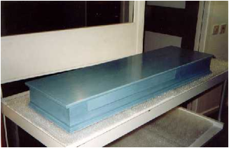
Delivery to Musikmuseet
In October, 1999, the clavichord was
delivered to Musikmuseet for incorporation in its collections. Hopefully, it
will be allowed to sound on different occasions. Here are some pictures from
the museum with the clavichord.

Some personal reflections
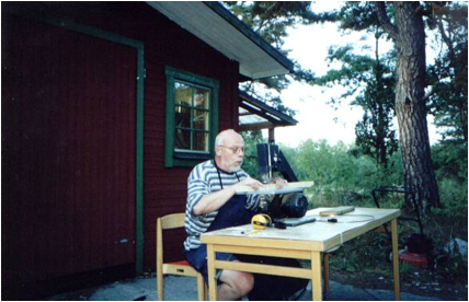
I built my first instrument, a clavichord kit from Carl Fudge, USA, at Marholmen in 1980, thus the second year of the course. I came there as a complete novice with only school woodworking as background. To build this instrument myself, of course with considerable help and support from HansErik Svensson, was a revelation. I learned to handle tools, acquired knowledge of materials, and solved problems of construction in a meaningful, stimulating environment. This became an immediate twenty-year-long passion and every course I learned something new. It has also been a fantastic experience to be able to make the learning trip - of course, it can be called a research trip - and the courses during these years have meant much. For my part, they have meant that a number of music instruments have come into existence during the course of these years: in 1984, a 10-course renaissance lute; in 1987, a guitar copied after Grobert; in 1992, a clavichord after Specken; in 1993, a baroque guitar after Deleplanque; in 1994, the stand for the Specken clavichord; in 1995, a 13-course baroque lute after Martin Hoffman; in 1998 a guitar after an original in my possession; and in 1999, a clavichord after an anonymous instrument in Musikmuseet. During the course of the years I have also devoted myself to renovation work of my own old instruments at Marholmen: three guitars and a fortepiano by Johan Gabriel Högwall.
One can perhaps wonder why I never
occupied myself with instrument building during the other parts of the year
rather than only during the opportunities I had at Marholmen. This is easy to
explain: Marholmen, with HansErik Svensson and Arne Lindberg as teachers, has
offered unique opportunities to dedicate oneself wholeheartedly and with all
one's body and soul to instrument building in a meaningful, stimulating
atmosphere, physically and psychologically. For my personal part, taking part
has implied relaxation and stimulation, and I have never found its equivalent
in another context. I would also like to state, or at least believe (others can
judge for themselves), that the Marholmen stays have had great meaning for my
personal development: an increased self-knowledge, increased ability with
handiwork and materials, increased respect for artisans of the past and for
their skill. I consider it as an extraordinary favor to have been part of the
courses at Marholmen.
The building of the clavichord copy for
Musikmuseet in 1999 went, from my point of view, exceptionally well. I had
first-rate wood to work with and it was a real joy to work with and shape it. I
worked more or less intensively about 10 hours a day, 7 days a week, building
the clavichord, which totaled in all about 170 hours. I am, however, a
reasonably experienced builder and not too finicky about details. It's
otherwise easy in instrument building to lose yourself in these details.
Different from lute building, there was a certain amount of repetitive part in
clavichord building (keys, stringing). The complexity of clavichord building
lies in making the mechanism function well and fine adjustments of the
tangents, the tangents' installation, working the listing cloth in, etc., which
are so very important for the resultant sound. I think that the evolutions of
things at Marholmen has been very interesting, and the characteristic sounds of
the instruments have been a very important aspect of the building. This
evolution has, therefore, not had to do primarily with producing instruments,
but also with attaining a certain quality of sound and successive improvements.
In 1999 the last of the instrument-building courses at Marholmen ended. The Birkagården Folkhögskola (Adult Ed center) thereby broke a 20-year-old tradition which was unique in the world. The stated reasons were economic, but it was perfectly obvious that the school's management lacked both the interest and the will to drive the enterprise farther. As an outside observer, I was enormously surprised and shocked over how the whole question had been handled by the management of the Folkhögskola.
Literature on the instrument-building course at Marholmen.
Printed works
Sparr, Kenneth, Konsten att bygga luta på 14 dagar [SGLS 18/1985
nr 3 s. 14-26]
Sparr, Kenneth, Gitarrbygge sommaren 1987 [Gitarr och Luta
21/1988 nr 1 s. 34-50]
Sparr, Kenneth, Instrumentbyggarkurs på Marholmen 1996 [Gitarr
och Luta 29/1996 nr 3 s. 4]
Sparr, Kenneth, Instrumentbyggkurserna på Marholmen - unika i
världen [Birkagårdens folkhögskola 80 år. Stockholm 1997 s. 25-40]
Articles on the Internet
Sparr, Kenneth, Instrumentbyggkurserna
på Marholmen - unika i världen.
Sparr, Kenneth, Musical Instrument Building Courses at Marholmen, Sweden - Unique in the
World.
|
©
Kenneth Sparr |